

cs2000
-
Posts
2,628 -
Joined
-
Last visited
Content Type
Profiles
Forums
Events
Gallery
Store
Everything posted by cs2000
-
Unfortunately different wheels and specs with the JR5 and JR11s YOu learn something new every day! I thought the figures you quoted me were a universal thing for every wheel. Seriously, offsets and the like boggle my noddle!
-
This is a quote from a PM I had with tarmac the other day. I have ordered a set or JR wheels in the fitment he advised to clear the Brembo calipers, and sit closer to the arch without the need for spacers.
-

The Bounty Bar Kids 350z parts clearout No. 1
cs2000 replied to The Bounty Bar Kid's topic in 350z Parts For Sale
Il take the mirror fold module please -
As in In Car Electronics I hope, not electrical rubbish :lol: ICE also stands for Internal Combustion Engine
-
[SOLD] Bluetooth Adaptor, Cradle & False Floor
cs2000 replied to cs2000's topic in 350z Parts For Sale
Now SOLD, mods please lock as required. -
[SOLD] Bluetooth Adaptor, Cradle & False Floor
cs2000 replied to cs2000's topic in 350z Parts For Sale
PM Incoming -
Another vote for Tarmac for me. Just bought an Invidia N1 from him a few days ago, along with a truckload of other bits! On a side note, Japspeed have a bit of a reputation round here, not a good one either. Just be aware that the cheapest 'proper' off the shelf system Tarmac do comes in at £660.00 (minus any forum discounts/deals), I have a powerflow system custom built on my Celica for £300. Yes it was only single exit, so probably add another 100-150 onto that for a Z as its dual exit. Not that this is a dig at Tarmac (far from it) just making you aware that off the shelf systems are far from cheap, regardless of the trader, aside from Japspeed, but there's a reason for that.
-
Not regarding me, but my other half works in the police (not going to say what role or what area for obvious reasons, but its nowhere near me!). Her late shift finished at midnight and just by chance a police officer in their traffic car was going the same way on their route as she was going home. She enjoys the odd "spirited" drive so they ended up having a little race together! The bad part is that the police officer actually tripped a GATSO camera, but obviously they just radio this in and it gets forgotten about! Not that I condone this ofcourse It was however gone midnight, on a 50mph section of straight dual carriageway in the dry, so whilst not legal, it was about as safe as a bit of spirited driving could be. Just makes me laugh that its not just the "boy racers" the police have a bit of fun too....sometimes!
-
I am currently building one, but if you can do the 3d modelling part then places like Shapeways will happily print something for you at a cost. The design is the element that take s along while however.
-
Cheers all. Hmm, I already have a truckload of parts on order from Tarmac, il drop him a message. Otherwise dipping may be a good idea
-
Hey all, I'm looking for some new, genuine floor mats to replace my ones as they're getting a bit tatty, could also do with a new boot one too if anyone knows where they're sold? I'm also looking for some carbon fibre B pillar covers, but I can only find crappy stickers, any ideas? Thanks all.
-
Hi All, Having upgraded my headunit to one with Bluetooth in it, I no longer have need for the Bluetooth module, therefore I have for sale the Bluetooth adaptor, the phone cradle and the false floor which it all screws into. Looking for £30.00 for the whole lot with £3.00 postage. Can be collected from the Ipswich area of Suffolk if the buyer is close. Thanks.
-
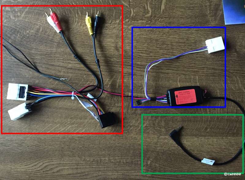
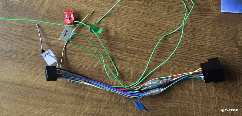
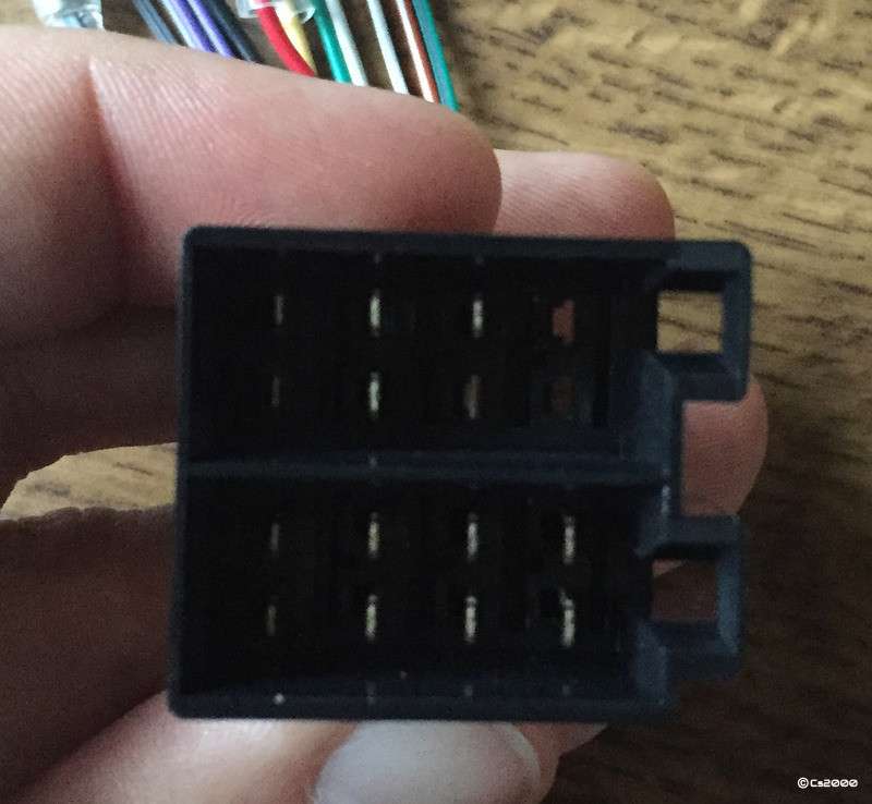
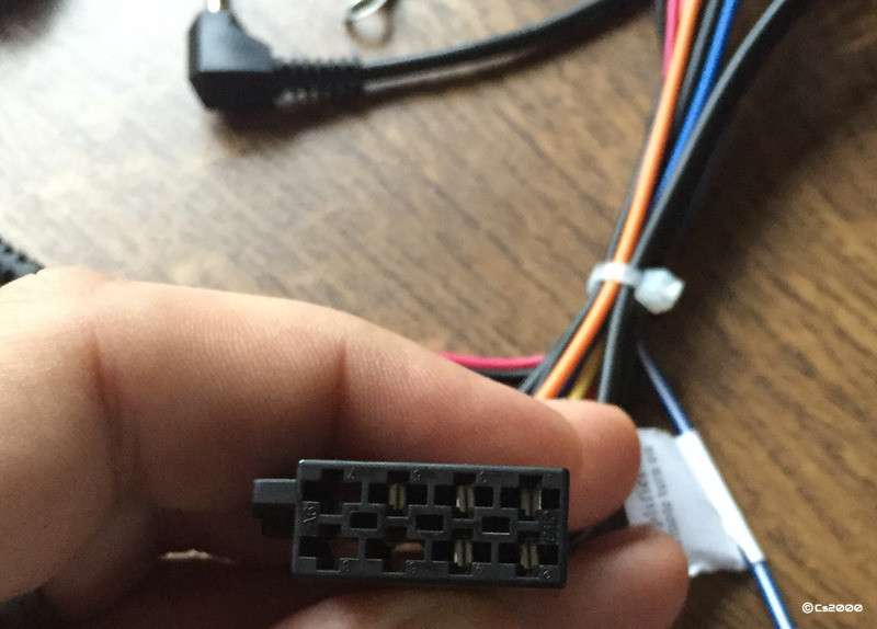
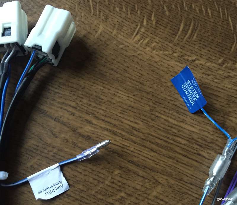
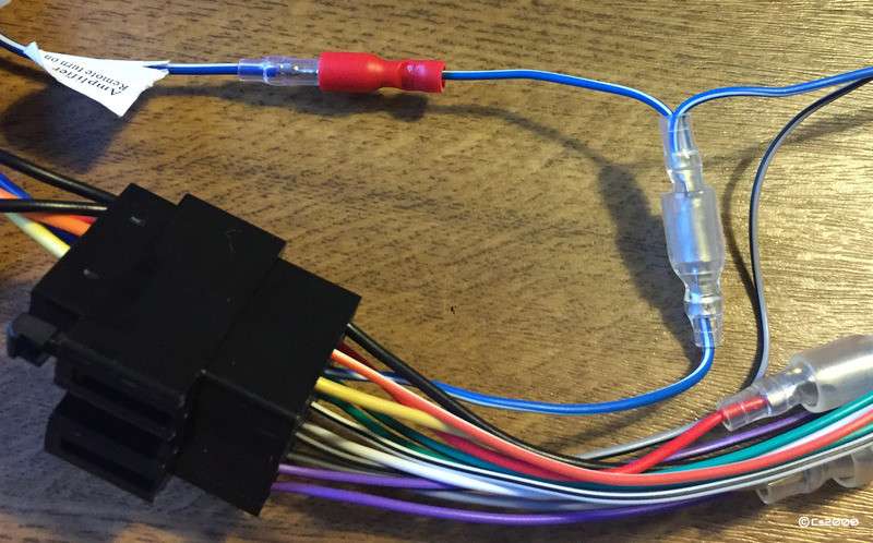
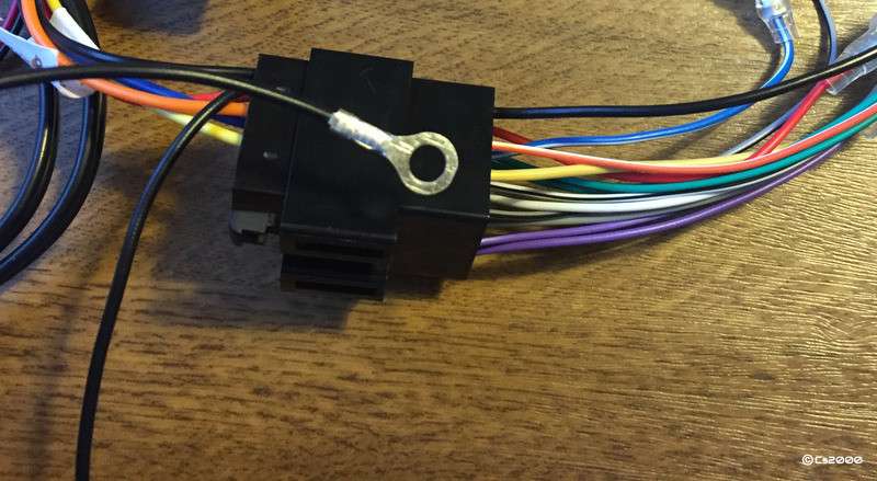
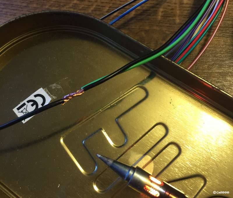
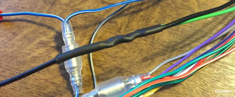
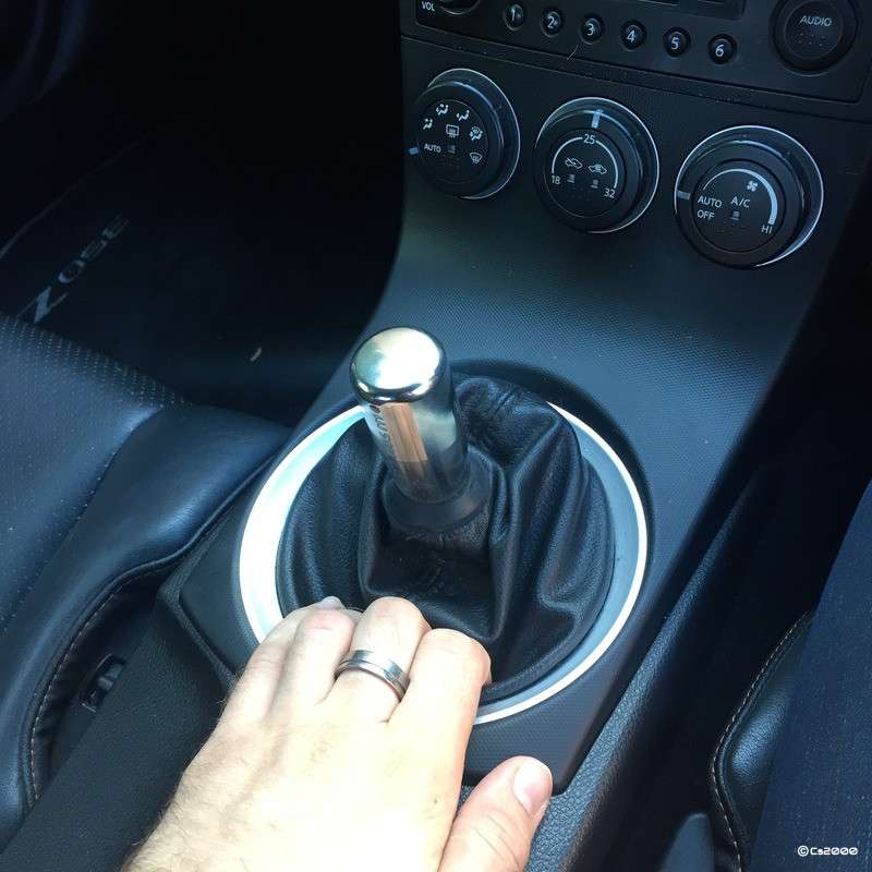
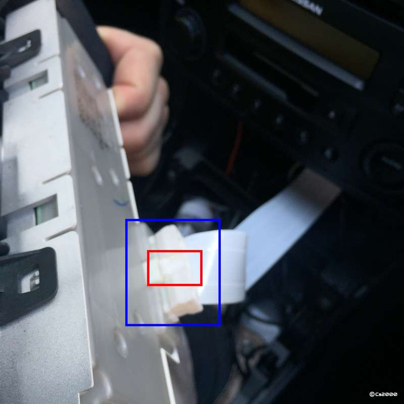
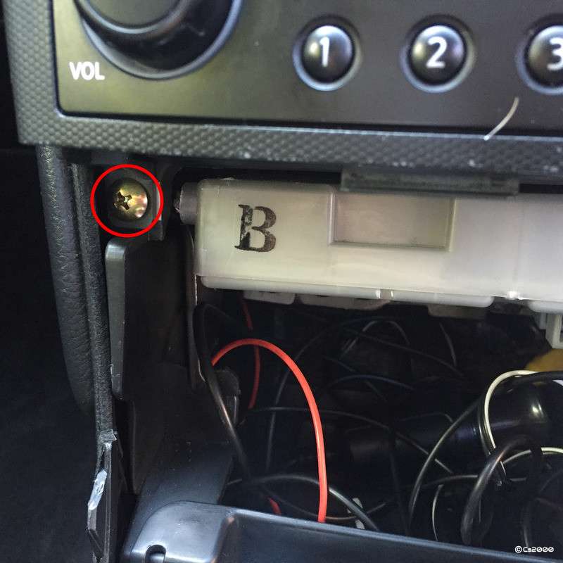
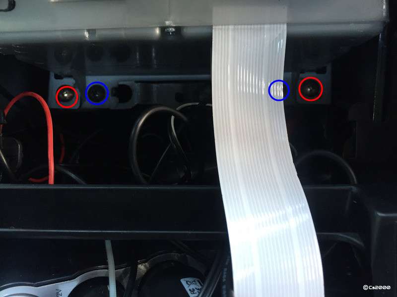
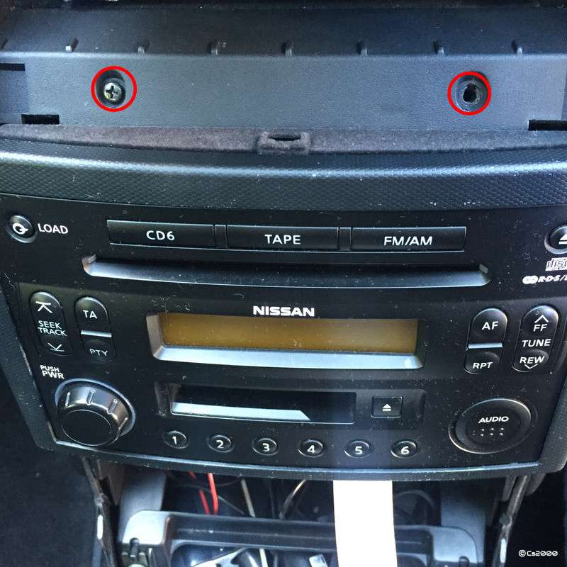
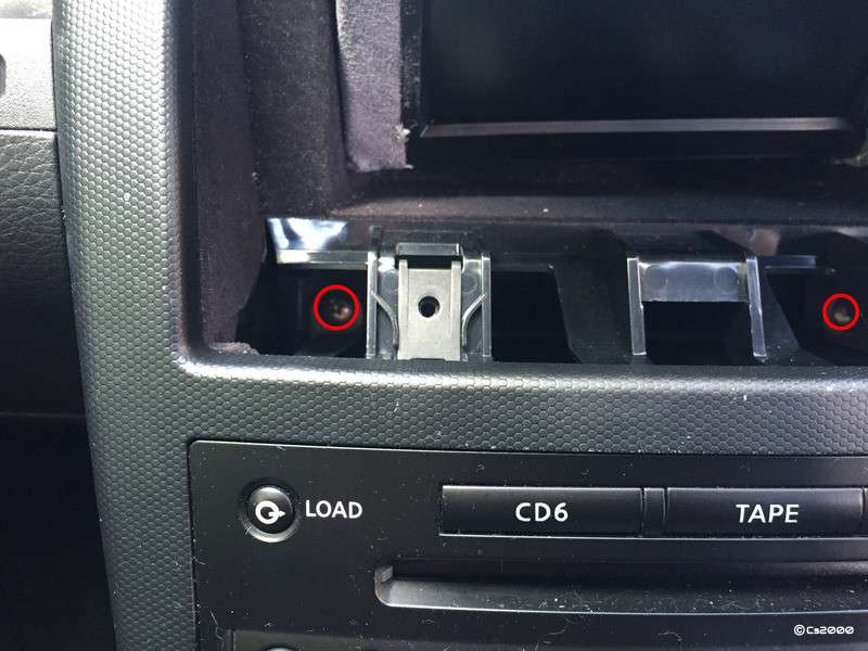
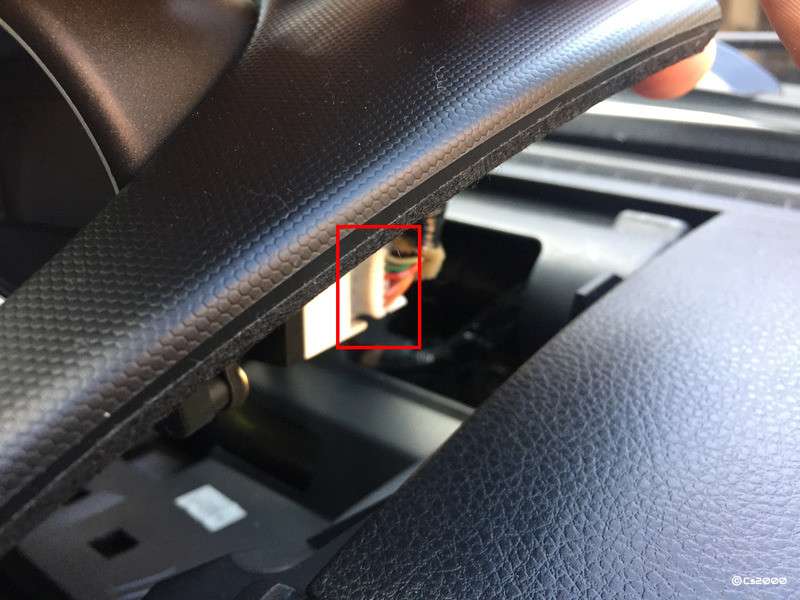
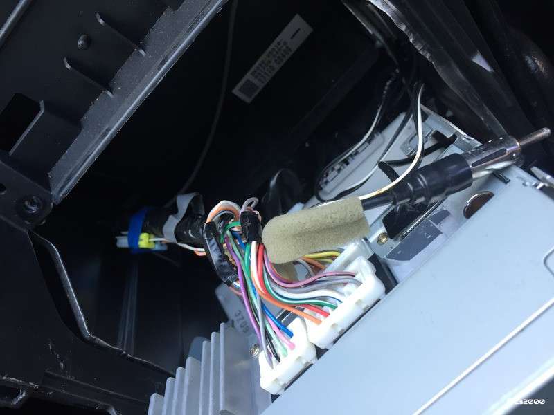
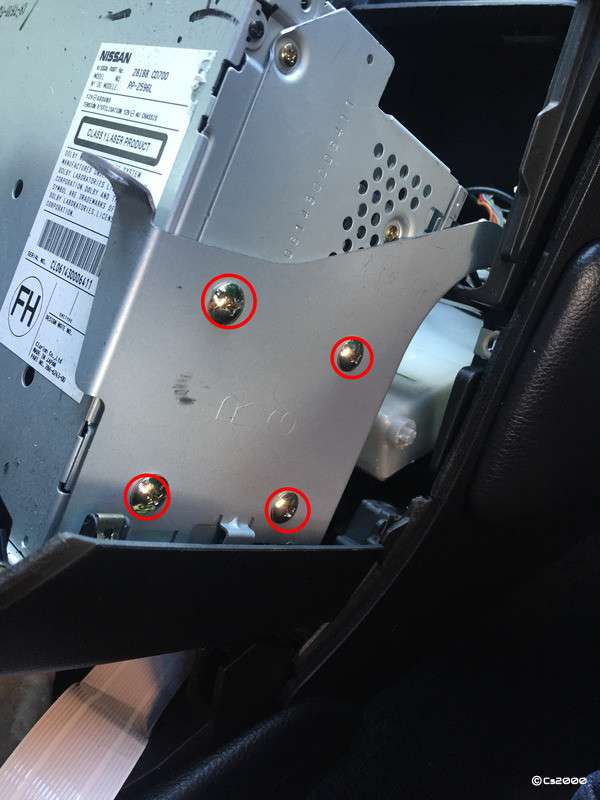
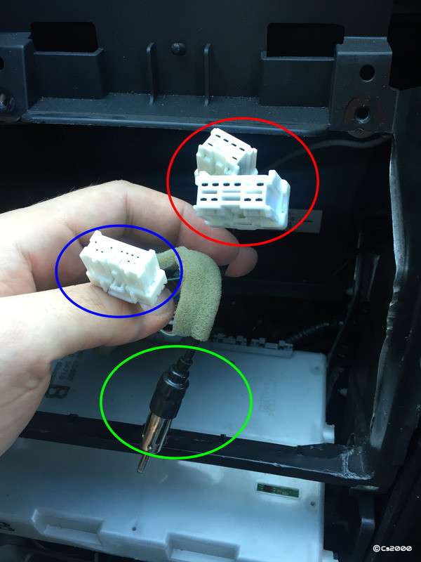
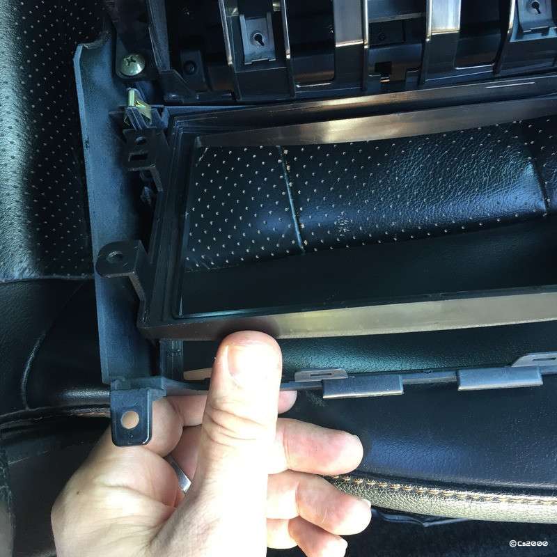
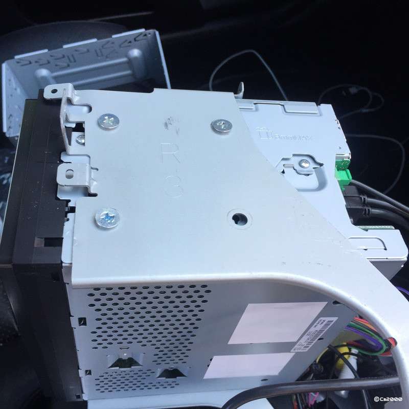
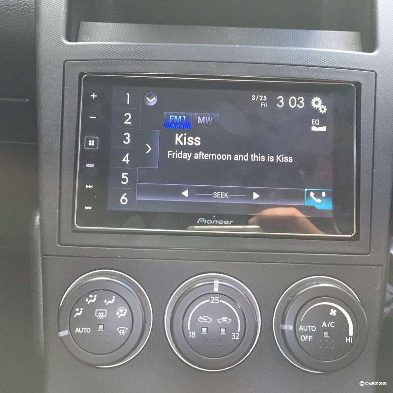
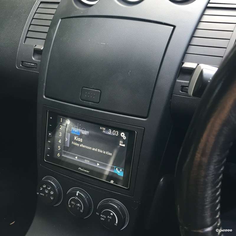
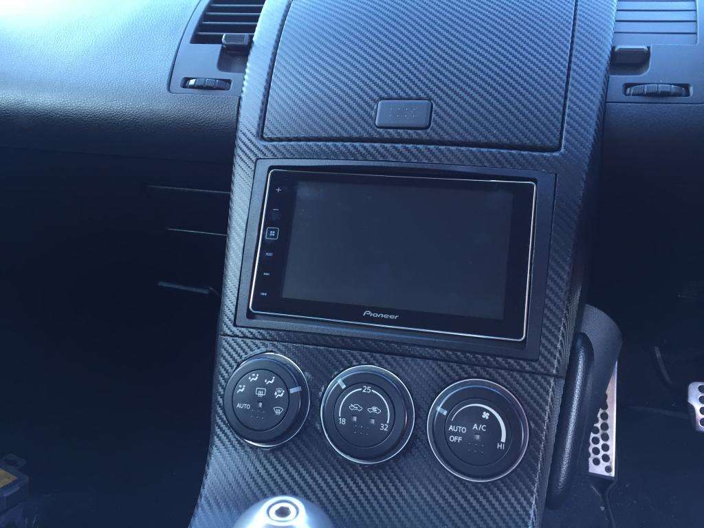
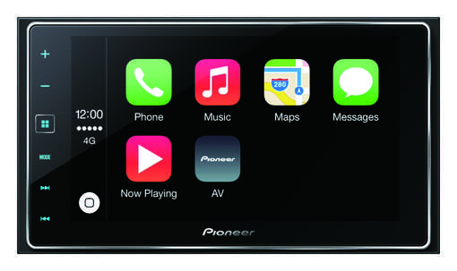
Hey all, I wanted to fit a new stereo to the Z and browsed the forums and online for a proper guide, but wasn't happy with any of them. They all seemed to be either out of date, or hastily written so didn't cover enough details. Hopefully this guide should patch up those flaws. It is written showing the install of a Pioneer SPH-DA120 AppRadio, but the basic principles apply for any stereo install. The cables we will be using will maintain the use of the original steering wheel controls for the audio control, but NOT for the Bluetooth (as is the case with any aftermarket headunit upgrade). In my case, this stereo is an AppRadio with Apple CarPlay so it totally replaces the stock Bluetooth dongle system which i will be removing along the way (but not documented). Tools/Materials Needed (your requirements may slightly differ) Screwdrivers (Magnetic ones make this easier) Trim Removal Tools Soldering Iron Heat shrink & Solder Bullet Style Cable Connectors Parts Required (prices correct at time of writing) All parts below are purchased from InCarTec (https://incartec.co.uk/Nissan/350Z/Stereo-Upgrade-Double-Din) 1 x Nissan 350z Bose Steering control interface - (29-674) £34.99 https://incartec.co.uk/product/Nissan-350Z-Murano-10-6-16-Pin-audio-steering-wheel-control-interface-29-674 Note, the next item is Pioneer specific, other models to suit other makes of head unit are available elsewhere on the site, they're listed on the product page of the previous item. 1 x PIONEER patch lead for 29 series SWC - (29-007) £3.99 https://incartec.co.uk/product/PIONEER-patch-lead-for-29-series-SWC-29-007 1 x Nissan 350Z Radio Facia Double Din - (50-256) £19.99 https://incartec.co.uk/product/Nissan-350Z-2003-2010-double-DIN-car-radio-fascia-adapter-panel-MATT-BLACK-50-256 Harness Identification So, lets begin with the Steering Control Interface & ISO Connector lead. The section shown in red is the lead allows connection between the cars factory head unit wiring and the stereo by converting it to a standard set of pins (for reference, cars wiring connects to the white sockets on the left, the standard ISO connector is the black plug on the right), this is then converted (by the lead included with your head unit) back to a custom connector to get the signals into the stereo itself. It also has a long black wire with an eyelet on it, this MUST be connected to a chassis ground in the car. This particular model has the section shown in blue as well. This box of tricks allow connection to the steering wheel controls. The blue section has the white plug which connects to the cars connectors. The section shown in green is just a jack plug that is the output of the steering wheel controls. This goes into the back of your head unit so it can receive the inputs/signals when you decide to use the volume or next track buttons on your wheel. The lead shown here is the head units wiring harness, this is included in the box of your new stereo. They are specific per model, so yours wont look the same, but should be similar. The are four things here to highlight are as follows; Long Green Wire - This is supposed to be wired to your handbrake switch. It disables certain functions unless you are parked up with the handbrake enabled. You can make your own choice, but I will be bypassing this "safety" feature. Short Purple & White Striped Wire - This wire takes an input from your reversing light to switch the screen to a backup camera image (if you have one installed) when reverse is selected. Its obviously optional to use this, but I will be doing so. If you don't have a reverse camera, just leave this wire alone. Red & Yellow Wires Connected with Bullet Connectors - One of these requires a constant 12v, the other requires a switched ignition feed. My advice is to simply leave these alone. If you find that your head unit stays on when you turn off the car, just swap these around so instead of going Yellow --> Yellow and Red --> Red, they go Yellow --> Red and Red --> Yellow. In my case, the standard setup was correct. Blue & White Striped Wire on Bullet Connectors - This is used normally to connect to external amplifiers and it controls the power on them (like a digital on/off switch). In our case, the 350z has a power antenna, so we need to use this wire for that. It also controls the power to the factory fitted BOSE amplifier on the GT spec cars. Connections (part 1) OK, so lets grab hold of the head units harness, notice the double stacked connector like this, the top having less pins than the bottom? The top set is used for the head unit power, ground and various other inputs, the bottom half is for the speakers (normally). Go ahead and grab the InCarTec loom, and find this black plug Notice how the pin count matches the top section. Go ahead and click them together. Harness Modifications So, we now need to slightly alter the harness. Step 1 - Connecting the on/off cable for the powered antenna On your newly connected harnesses, you should now have two loose white & blue striped wires like the photo below. For reference, the InCarTec loom is the left, the Pioneer loom is on the right. These need to be joined to allow the antenna to receive power when the head unit is turned on. Despite how it looks if you look at the loom, in standard configuration these aren't connected (I verified this using a multimeter set to continuity). As you can see, I simply crimped on a bullet connected and pushed them together. If you don't have one of these you can cut and solder them together. Step 2 - Bypassing the parking brake detection on the head unit Note: Manufacturers add this 'safety feature' for a reason. Its up to you whether you choose to bypass it. Im not sure of any legal or insurance related implications to doing this, so make up your own mind. Bypass methods vary between manufactures and even models, so if you do carry this out, check that yours is as simple as this. Some models require relays to be connected instead of this method! So, locate the grounding wire. On the InCarTec loom, it is black and has the little eyelet on it. You should be able to follow this back through the connection block and see it matches up to the black wire on the head unit loom. Locate the green parking brake detection wire on the head unit loom. Cut this, and the black cable on the same loom to the same length and twist together as shown. Solder these connections together and seal with some heat shrink Lastly, I have never had to do this before, but it turns out that because the Z has a amplifier built into it, the adaptor cables that you buy mean you have to connect your speakers with the phono cables, rather than the usual set of + and - wires that speakers come with (which would normally connect to the lower half of the ISO plug adaptor shown earlier. The issue with this is that it means the speakers are only provided with 4v, rather than the usual 12v. You can correct this 'issue' by following busters harness modification linked below. I have now written a proper guide for this available below. http://www.350z-uk.com/topic/107583-how-to-busters-rca-headunit-volume-fix-guide/ I personally have done this mod, but as you can see from the guide above I hacked up another connector from another 350z ISO wiring loom so if i want to unplug this from the car im still able to do so as nothing is soldered in. Your call. If you dont do this mod, you will have lower sound levels, and remember to actually connect the phono leads! Busters original topic is below, my guide is above. http://www.350z-uk.com/topic/58947-reduced-sound-out-put-after-replacing-oe-bose/ Anyway, the wiring harness modifications are now complete. You should now have a single black plug to connect to your head unit. One white plug with only 3 or 4 pins in it to connect to the Zeds steering wheel controls and two white plugs with lots of pins to connect to the factory stereo wiring. The last job to do is connect this bundle of wires to your stereo. This will vary per head unit, so I wont bother to describe it, but in my example, it was a single large black plug for all of the audio, power and control stuff, then a single 3.5mm jack for the steering wheel controls, plus another plug for the GPS antenna, some USB connectors and an AUX in. Connect this up following the head units instructions and then its onto the install. Out With The Old OK, so the first step here is to free the central part of the dash. This is held in by a total of 6 screws, with only two other things in the way. First, remove the gear gaiter surround by pulling up on the silver ring as shown, then just twist this part and leave it dangling around the passenger foot well area. You may then want to put the car into 2nd, 4th, 6th or reverse as it gives you another inch or so of free space to work with. Next, you need to remove this white ribbon cable as shown in blue. To remove it, press the clip down firmly (shown in red) and pull away from the unit. Be careful with this as the ribbon cable can tear with relative ease. Then, you need to remove these two gold coloured screws on the lower part of the dash, one is shown here in red, the other is just on the other side. Remove these and keep them safe Next, we have four screws again on the lower part of the dash. The gold ones, here shown in red, hold the head unit mounting bracket to the car, the black ones here shown in blue hold the A/C control box (the big white thing) in place. This gets in the way of removal of the stereo, so you just need to remove these 4 screws and leave the A/C control unit dangling free for now. Next, open the cubby hole in the centre of the dash, pull the rubber mat upwards and you will now see 2 screws. These hold the plastic piece in place which acts as the locking mechanism for the cubby door, but they also hide a further 2 screws we need to remove. Therefore, remove the two screws (locations shown in red) and then lift out the plastic piece. Now we can see the last of the two hidden screws, they should be gold in colour and are shown here in red. You will need a magnetic screwdriver to get these out, or you will more than likely drop them and loose them behind the dashboard! NOTE: With your new unit, you MUST attach the ground wire. Using my multimeter I have found that the bracket that these two screws fix into is actually grounded. Therefore, on assembly of the wiring harness, I attached the eyelet from my ground wire to this screw, providing the head unit with a ground. The centre dash is now free from the car. Start to pull it out from the bottom to the top slowly and carefully. Once you get to the top, you will need to undo the white connector shown here in red. It has a VERY short lead so don't pull it, but to remove it, you need to press the little plastic lock which will be facing the windscreen. It works the same way as the heater control ribbon cable from earlier, its just a little tricky because you cant actually see the clip. Anyway, remove this and then carefully remove the entire of the centre dash. Once freed, you can now see the rear of the BOSE head unit. Remove the three white plugs by pressing down the little clip (same as all the others) and pulling. The black antenna connector just pulls out of its socket (it fits a bit like a 12v car charger fits into its socket) Now we need to free the old unit from the cars mounting brackets. You should now be able to remove the entire of this large centre dash out of the car which will make this easier. Anyway, remove the 4 screws shown here in red, do the same the other side and carefully remove the BOSE from the mounting brackets. All old items should now be removed, so if we're all ready, let's move on. NOTE: The BOSE head unit is 'Married' to your car. Unless properly removed and de-registered (which isn't something you can do) it wont work in any other vehicle. Just a reminder in-case you were thinking of selling it. In With The New So now we can see our cables properly. The two red circled plugs send data for power & ground etc, and for the speakers, the third plug shown in blue is for steering wheel controls and the fourth black one shown in green is for antenna. You need to now connect these to your new wiring harness that we prepared earlier. The plugs all only fit 1 way, so don't be scared of this step. Also fit the antenna into the new head unit by simply pushing it into its slot. NOTE: Remember to attach the ground wire at this stage! You can attach it anywhere you want, but as I mentioned, the screws that you removed that were hidden behind the cubby are actually attached to a grounded bracket, so id advise you use these. I didn't take any photos of this stage, but you must now remove the factory mounting brackets from the dash piece so we can fit our new facia adaptor. These are simply held in place by a single black screw on either side. Remove these and then lay down the facia adaptor into its hole. NOTE: As-long as you've grounded the unit, now is a good time to turn the car on and test the head unit. Just ensure it powers on, sound can be heard out of the speakers, the steering wheel controls work and it powers down when you turn it off again. If your head unit required any other connectors such as a GPS antenna, rear aux in, USB input or a reverse camera, attach these now as well. You can now fix the brackets you just removed onto your new head unit. The unit SHOULD come with new screws, so please use these if it does. My unit had several holes drilled on the sides, each with a letter. The manual told you which holes to use for which manufacturer of car. Mine were all labelled 'N' for Nissan . Fit the screws but don't tighten them all the way up for now. Again, no photos here, but you can now place the head unit with its new mounting brackets back into its location on the dash piece. You need to re-secure this with the two black screws you removed earlier. Adjust the position of everything so it all fits square in its new home and fully tighten all 6 of the head unit screws and the two black bracket mounting screws. Assembly Is The Reverse Of Disassembly Yep, i hate that saying too, but it kinda is. To re-assemble you need to carefully put the centre dash piece back into the car. Your first task is to stuff the whole bunch of new wires into their home which is usually relatively difficult as space is tight. Next, look at the bottom part of the dash and get the two metal 'legs' back in the right place behind the white heater control box, re-attach the two gold screws. Now re-mount the heater control box in its home, and re-attach using the two black screws. Screw in the screws hidden behind the cubby hole again using your magnetic screwdriver to hold them as you find the hole. (Remember the earth wire should be screwed in with one of these!) Clip in the electrical connector for the three centre pod gauges. Re-attach the two gold screws that are right at the bottom and towards the front of the centre dash piece. Put the plastic latch mechanism back in the cubby hole and re-attach the two black screws. Remember to lay down the rubber mat back into here once done. Completion That's it, your job is now complete. Below are two pictures of my finished install. Overall, its quite a simple job as-long as you have the right harness. For me, total install time including wiring in all my extras was around 3 hours, and harness modification (as I also bypassed the phono cabled) was about 1.5 hours, obviously your mileage may vary. Hope the guide is of help, and any questions please just ask
-
If you aren't using the bose amp, you can just get the standard ISO lead that is for non bose fitted cars
-
This, they don't lift the bonnet. They do assist, and do hold it open, but don't lift it themselves like boot struts too.
-
Just for reference my '08 HR did not have threadlock on them, but did require quite a force to start them off but easy once started. Thanks for that update. Mine definitely must have lots of threadlock on them because they show no signs of shifting at all. I have decided to check to see if the weight is still in the bootlid and, if so, remove it as a first step. Failing that, I will try to cut the sockets off the ball joints and replace the struts using the OEM ball joints. Theres no need to cut them off!! If you look at the strut where it clips onto the ball joint, you will see a thin black metal band going around the strut/ball joint socket area, if you use something like a knife to lever this off of the strut (its clipped in somehow, but cant remember how) the strut will come free from the ball joint if you give it a little tug as there's nothing physically holding it in place anymore. Just bear in mind, the single strut that's still attached can NOT hold the boot up, it is very heavy so don't let it hit you on the head when you take the first strut off. Unless youre primed ready for it, or have a helper it will do just that!
-
Yep, got back tonight and the InCarTech 29-674 harness is the correct one. Another reason why I will be writing a guide for this as the ones we already have are terribly out of date.
-
It is indeed a 12mm bolt. When i fitted my struts I removed the OEM one, but they are held in very tightly with copious amounts of threadlock. Personally, I heated the ball joints up with the "flamethrower" tip on my gas soldering iron (you could also use a kitchen blowtorch) to try to soften the threadlock, then used an open ended 12mm spanner (not a socket or the round end ones) and it came off with a bit of force.
-
I think this is all the endorsements you need to be fair.
-
That's a loose ribbon cable deep down inside the Bose HU, it can be repaired, but isn't east to get at. Ive just cured mine...by purchasing a Pioneer SPH-DA120 (it has Apple CarPlay ) How the SPH-DA120 looks in mine.... Cant believe you have the same unit! lol Quick question in that case. The facia that comes on the unit as standard, did you use it, or do you use the adaptor that you have to buy separately?
-
Hi all, I bought a pioneer AppRadio yesterday, but am struggling to wrap my head around what ISO wiring harness I need. I really want to stick with the Autoleads brand if possible as they've available at my local halfrauds (and I want to fit it this weekend). I have already bought the PC2-76-4, but upon further inspection the product detail says "This lead is for the NON-AMPLIFIED systems on these vehicles only", and obviously the Bose has an amp, so wont work. Is anyone able to assist with finding the right adaptor, again preferably Autoleads so I can collect it today/tomorrow, but if not, any that fit! EDIT: I just realised, I have actually bought the InCarTech 29-674 loom for the steering wheel controls (with the added pioneer patch lead), it looks like this combines an ISO adaptor, am I correct here??
-
And again, just to add my 2p, I had a line fail last year. http://www.350z-uk.com/topic/101042-hel-braided-brake-lines-failure/ These were installed by Sly at Kaiser Motors so id hardly blame bad installation. I have now got a set of the goodridge lines which are at least 40% longer and come with proper mounting brackets and proper fixings rather than the banjo fittings the HEl ones have In my case with the HEL's I suspect the P clamp they supply over time wore away the insulation on the outside, as soon as this is gone the inner Teflon tube cant support the pressure and it splits. Id never touch them about with a barge pole of any length! I am fully aware that there are many thousands of happy customers, and mine is just 1 failure, but the failure of a braking component is unacceptable IMO.
-
Well, I will document mine as I'm not 100% happy with any of the install guides ive read so far. I know what I'm doing having done 2 or 3 stereos in the past, but I was just brushing up on anything Z specific, so you will be able to see how I get on (along with how good/bad the facia adaptor sits/looks).
-
That's a loose ribbon cable deep down inside the Bose HU, it can be repaired, but isn't east to get at. Ive just cured mine...by purchasing a Pioneer SPH-DA120 (it has Apple CarPlay )
-
I took my wheels off, lightly sanded the hubs so it was rust free and then painted them black with a few coatrs of hammerite. The rust has never came back after 2 years or so and they just kinda disappear then
